The moment a boat has two helm displays, a radar, a live sonar and a networked autopilot, the Ethernet network behind them stops being an afterthought. A poorly planned network shows up as a frozen radar picture, sonar that stutters, a second display that “loses” the first, or a chartplotter that takes minutes to share waypoints. Almost every one of those faults traces to the same short list of causes: the wrong switch, a cable past its length limit, a connector that let water in, or two systems sharing a network that were never meant to. This guide explains how to design, build and test a marine Ethernet network for multiple displays on a center console or offshore fishing boat, with the cable specs, switch choices and checks we use on installs.
How a marine Ethernet network works
Marine Ethernet uses the same principles as a home network: each device has an address, devices connect through switches and traffic is passed as packets. The differences are the environment and the connectors. Marine devices use sealed, locking connectors such as Garmin’s marine network connectors, Lowrance and Simrad’s five-pin Ethernet or Raymarine’s SeaTalkhs/RayNet. These resist water and vibration but are not interchangeable, so you often need adapter cables.
| Device | Typical traffic | Bandwidth demand |
|---|---|---|
| Chartplotter / MFD | Charts, waypoints, sonar and radar sharing | Moderate to high |
| Open array or dome radar | Continuous sweep data | High |
| Live forward-facing sonar | Real-time imaging stream | High |
| Autopilot controller | Small control messages | Low |
| Audio PartyBus | Streaming audio and control | Moderate |
Planning the network
- List every device that needs Ethernet and note its connector type.
- Decide where each display and the switch will mount, then measure cable runs along the actual route.
- Choose a switch with enough ports plus spare capacity for a future upgrade.
- Plan power: the switch and some devices need their own fused 12 V supply.
- Label every cable at both ends before it is pulled.
Installer Tip: A single run of Cat5e or marine Ethernet cable is limited to 100 m by the Ethernet standard, but real boats rarely approach that. The practical limit is almost always connector adapters and bends in the route, not length. Keep each run as short and straight as you can.
Direct connection or switch?
With two devices, a direct cable between them usually works. As soon as you add a third (a radar, live sonar or a second display), you need a network switch. Daisy-chaining devices through a display that is acting as a pass-through is fragile: turn that display off and everything behind it disappears.
| Setup | Good for | Weakness |
|---|---|---|
| Direct cable, two devices | Simple helm plus one MFD or sonar module | No expansion |
| Single marine switch (4 to 8 ports) | Most center consoles with two displays, radar and sonar | Switch is a single point of failure; mount it dry |
| Two switches linked | Larger boats with a helm and a tower or flybridge station | More cabling and power points to manage |
| Managed switch | Mixed audio, camera and navigation traffic | Cost and set-up complexity |
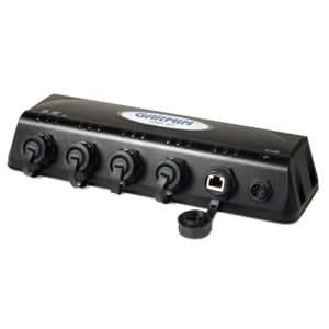
Choosing a switch
- Use a marine-rated or manufacturer-approved switch: a cheap office switch is not designed for 12 V, vibration or moisture.
- Look for gigabit support if you run live sonar and radar: 10/100 Mbps is enough for some systems, but gigabit leaves room for growth.
- Check the power input range: choose a unit that tolerates the 9 to 16 V range of a boat’s electrical system.
- Mount it high and dry: the dash or inside the console, not in a bilge or beside a hatch that leaks.
Cables, connectors and routing
Cable standards
Use cables made for marine use with the correct connector at each end. If you must adapt between connector types, use a purpose-made adapter cable rather than a home-made splice, and keep adapters inside a dry location. Garmin cables, for example, use a different connector from Lowrance or Simrad cables, so a Garmin-to-Lowrance bridge is not plug-and-play. Our Garmin marine network cable is a typical example of a ready-made run for Garmin systems.
Routing
- Keep Ethernet at least 30 cm (12 in) from high-current cables, alternator leads and VHF coax.
- Use grommets and drip loops at every bulkhead and connector.
- Do not exceed the minimum bend radius, typically about four times the cable diameter.
- Avoid tight cable ties that crush the cable and cause intermittent faults.
Power and grounding for the network
Run the switch from a dedicated, fused supply. For a 1 A load over a 4 m run, 1.5 mm² (16 AWG) cable drops about 0.09 V, well within the 3% limit. Check the formula Vdrop = 2 × length (m) × current (A) × 0.0172 ÷ area (mm²), and use a common negative bus for the whole system. Our voltage drop guide covers longer runs.
Setting up the displays
- Update firmware on every display and module to the latest version the manufacturer recommends, since sharing features change between versions.
- Power up one display at a time and let it find the network.
- Check each device’s name and instance so you can tell them apart (Helm, Tower, Radar).
- Confirm that sonar, radar and chart data appear on each display and that waypoints sync.
- Test with each display switched off to confirm nothing else depends on it.
Troubleshooting
| Symptom | Likely cause | Fix |
|---|---|---|
| Radar or sonar will not appear on the second display | Wrong cable or adapter, or mismatched firmware | Check the connector type; update firmware |
| Picture freezes or stutters | Overloaded network or poor cable | Move audio or cameras to their own switch; replace cable |
| Network drops when a display is turned off | Daisy-chain through a display | Add a switch |
| Intermittent fault in wet weather | Water in a connector | Reseat and seal the connector; replace if corroded |
| Devices keep the same name | Duplicate names | Rename each device in the network settings |
Keeping it maintainable
Take photos and notes of the finished network, with the switch port assigned to each device, and keep them aboard. When a new device is added, plug it in, update the notes and test. Our NMEA 2000 guide covers the separate control network that runs alongside, and our GPSMAP vs HDS PRO comparison shows how large MFDs share data. Browse electronics and power for switches and cables, and contact our team for help drawing up a network for your boat.
Wireless features and remote access
Most current displays offer Wi-Fi for chart downloads, firmware updates and remote control from a phone or tablet. This wireless link is separate from the wired network that carries radar and sonar. Keep the wired network on its own switch, and do not bridge the boat’s navigation network to a marina Wi-Fi or a cellular router without understanding what that exposes. Use a strong password for the display’s access point and update firmware regularly to receive security fixes.
Documenting your network
A simple table saves hours the next time something fails. Fill it in at installation and keep a copy aboard.
| Port on switch | Device | Cable length | Connector type | Notes |
|---|---|---|---|---|
| 1 | Helm MFD | 2 m | Manufacturer marine connector | Primary display |
| 2 | Radar | 12 m | Radar network connector | Open array on arch |
| 3 | Live sonar module | 6 m | Sonar network connector | Powered from separate fuse |
| 4 | Tower MFD | 9 m | Manufacturer marine connector | Second display |
Planning for growth
Leave at least two spare ports on the switch, and run a spare network cable to the tower or bow when you are pulling cables anyway. A spare cable costs very little when the panels are open and a lot when they are not. If you expect to add live sonar, an autopilot or a camera, plan the power supply and fuse capacity for them now.
Commissioning checklist
- Label every cable at both ends and fill in the port table.
- Power up the switch first, then each device in turn.
- Check link lights on each port to confirm a connection.
- Update firmware on all displays and modules.
- Confirm sharing of sonar, radar and waypoints on every display.
- Switch off one display at a time and check that the others carry on.
- Take photos of the finished layout for your records.
Ten minutes spent on this list at the dock saves hours of troubleshooting on the water.
Frequently asked questions
Do I need a network switch for two displays?
With only two devices, a direct cable may work. When you add radar or live sonar, a switch is the reliable approach and avoids daisy-chaining through a display.
Can I use an ordinary Ethernet switch on a boat?
It is not recommended. Choose a marine-rated or manufacturer-approved switch that tolerates a 9 to 16 V supply, vibration and moisture, and mount it in a dry location.
What is the maximum Ethernet cable length?
The Ethernet standard allows 100 m per run, but connector adapters and routing make shorter runs more reliable on a boat. Keep each run as short as practical.
Why does my radar freeze on the second display?
Common causes are a wrong or damaged cable, a firmware mismatch or an overloaded network. Check connectors, update firmware and consider moving audio or cameras to a separate switch.
Leave a Reply