Category: Installation & Setup

  • How to Prevent Marine Electronics Voltage Drops & Sonar Interference: Nocqua Lithium Power, NMEA 2000 Backbones, Glass Screen Protection, and Clean Power Busbars

    There are two kinds of marine electronics problems. The first kind is equipment failure — the unit stops working. The second kind is installation failure — the unit works, but it performs 30% below its capability because the power is dirty, the network is noisy, or a screen is scratched to the point of being unreadable in direct sun. The second kind accounts for most of the frustration anglers report with live sonar and chartplotters.

    This guide covers four areas where installation quality has the biggest impact on electronics performance: lithium power sizing (especially for kayak setups using Nocqua), NMEA 2000 backbone architecture, sonar interference prevention, and screen protection.

    Part 1 — Sizing Nocqua Lithium Power Kits for Kayak Sonar & Live Sonar

    Why Kayak Electronics Need Dedicated Lithium Power

    A bass boat runs its fish finders from a dedicated 12V accessory battery, isolated from the cranking battery. Kayaks don’t have this. The options are: a small sealed lead-acid battery, a USB power bank, or a dedicated lithium kayak power kit. SLA batteries are heavy (6–8 lb for 7Ah) and sag under load. USB power banks max at 2–3A — not enough for live sonar. A dedicated kayak lithium kit — the Nocqua Pro Power Kit line — is the right solution.

    Nocqua Pro Power Kit Specifications

    Nocqua 10Ah Pro Power Kit: 10 amp-hours at 12V (120 watt-hours), up to 8A continuous output, ~1.8 lb. Best for a single fish finder without live sonar (Garmin ECHOMAP UHD2, Lowrance Eagle Eye, Humminbird HELIX 7/9). Recharge: 2–3 hours.

    Nocqua 20Ah Pro Power Kit: 20 amp-hours at 12V (240 watt-hours), up to 10A continuous, ~3.2 lb. Best for a single display + LiveScope Plus (GLS10 draws 2.5A + display ~2–3A = 4.5–5.5A total), or dual display rigs.

    Calculating Which Nocqua Kit You Need

    Add up the current draw of everything powered by the battery:

    Device Typical Draw at 12V
    Garmin ECHOMAP UHD2 6sv ~1.8A
    Garmin ECHOMAP Ultra 2 12″ ~3.0A
    Garmin GLS10 (LiveScope black box) ~2.5A
    Lowrance Eagle Eye 9 ~1.5A
    Lowrance ActiveTarget 2 module ~1.2A
    Humminbird HELIX 9 ~1.8A
    Humminbird MEGA Live transducer ~1.0A

    Example 1 — Eagle Eye 9 only: 1.5A × 10 hours = 15Ah minimum. Use Nocqua 20Ah.

    Example 2 — ECHOMAP UHD2 6sv only: 1.8A × 8 hours = 14.4Ah. Use Nocqua 20Ah for a full day; 10Ah for a half-day.

    Example 3 — ECHOMAP UHD2 6sv + LiveScope Plus: (1.8A + 2.5A) × 6 hours = 25.8Ah minimum. Use two Nocqua 20Ah kits wired in parallel (same 12V, doubled capacity to 40Ah).

    Shop Nocqua Power Kits →

    Part 2 — Mapping a Clean NMEA 2000 Backbone

    NMEA 2000 is the data network that connects fish finders, GPS antennae, VHF radios, autopilots, and live sonar black boxes. When installed correctly, all devices communicate seamlessly. When installed wrong, you get random dropouts, false depth readings, and live sonar freezes.

    The Rules of NMEA 2000

    Rule 1: The Backbone Is Not a Star. The backbone is a linear bus — one cable running bow to stern with devices connected via T-connectors and short drop cables. Do NOT run individual cables from each device back to a central hub. That’s a star topology and causes signal reflections.

    Rule 2: Terminate Both Ends. The backbone must have a 120Ω terminating resistor at each end. Forgetting a terminator causes signal reflections that corrupt data across the entire network. NMEA 2000 starter kits include two terminators — install both.

    Rule 3: Maximum Drop Cable Length Is 6 Meters. Each T-connector drop cable running to a device must not exceed 6 meters (~19.7 feet). Longer drops create reflection issues.

    Rule 4: Power the Backbone Once. Connect backbone power at one T-connector near the middle of the run. 12V accessory circuit, 3A fused. Multiple power injection points create current loops and can damage devices.

    Important — GLS10 current draw: The Garmin GLS10 draws 2.5A from the backbone bus. If you have an older NMEA 2000 starter kit with a 2A power cable, upgrade to the Garmin 010-11442-00 starter kit rated for GLS10 before installing LiveScope.

    Recommended Device Order on the Backbone

    For a typical bass boat with bow-mount trolling motor, run the backbone port side from bow to console:

    1. Bow Terminator
    2. T-connector → LiveScope GLS10 (mount in bow locker, shortest possible drop)
    3. T-connector → ECHOMAP Ultra 2 at bow
    4. Backbone runs to console
    5. T-connector → Backbone power cable (12V, 3A fused)
    6. T-connector → VHF radio or Standard Horizon GX1800
    7. T-connector → ECHOMAP or GPSMAP at console
    8. Stern Terminator

    Position the GLS10 as close to the bow display as possible — LiveScope data has the highest bandwidth on the NMEA 2000 bus and benefits from the shortest cable path to the display.

    Part 3 — Preventing Sonar Interference at the Electrical Level

    The Three Sources of Sonar Noise

    Source 1: Trolling Motor EMI. Brushed trolling motors generate EMI that overlaps with fish finder sonar frequencies. Appears as “V” shapes or horizontal streaks that track with motor speed. Fix: Upgrade to a brushless motor (Ultrex Quest, Force Pro, or Ghost X). If keeping a brushed motor: install ferrite choke cores on the power leads where they enter the boat. Run the fish finder on a separate battery from the trolling motor.

    Source 2: Engine Alternator Noise. Appears as a horizontal bar that changes pitch with RPM. Fix: Dedicated fused circuit for the fish finder, separate from motor circuits. Add a marine-grade DC noise filter inline on the fish finder power lead.

    Source 3: Other Boats’ Sonar. Random streaks from shared frequency bands in tournament conditions. Fix: Enable CHIRP on your transducer. Set Interference Rejection to Medium in display settings (Garmin: Low/Medium/High; Lowrance: SideScan Reject; Humminbird: SI Noise Filter). On LiveScope specifically: Medium is the standard tournament setting — High reduces range slightly but cleans up dense environments.

    The Clean Power Busbar — Eliminating All Electrical Noise at the Source

    The most effective single improvement for marine electronics electrical noise is installing a properly isolated power distribution busbar — specifically a Blue Sea Systems PowerBar (5026).

    The concept: every device on your boat shares the same 12V battery. If they’re all wired directly to the battery terminals, they share ground connections — and noise from one device (pumps, lights, trolling motor) travels back through the shared ground to every other device. A properly installed busbar separates these circuits:

    • One positive busbar → individual fused circuits to each device (fish finder #1, fish finder #2, GLS10/AT2 module, VHF, lighting/pumps)
    • One negative busbar ← individual negative returns from each device

    The Blue Sea Systems 5026 PowerBar includes 12 fused circuits, a common positive bus, and connection points for a separate negative bus. A fault in one circuit doesn’t affect the others, and the shared ground path through the negative busbar carries no high-current motor noise. Shop the Blue Sea Systems PowerBar →

    Part 4 — Glass Screen Protection

    Why Tempered Glass — Not Plastic Film

    Fish finder screens take abuse: sand and grit from wet hands, tackle boxes sliding across the console, six months of direct UV per year. The factory lens is typically polycarbonate — it scratches within a season of regular use. Once scratched, anti-reflective coatings fail and direct-sun readability drops significantly.

    Plastic film protectors trap bubbles, peel at edges in marine environments, reduce touch sensitivity, and add a visual layer between your eye and the display. Not recommended for $1,000+ units.

    RMP Tempered Glass protectors are optically-bonded, precision-cut for each specific display model. Zero visual distortion, full touch sensitivity maintained, rated for marine UV and salt exposure, 9H scratch resistance. The gold standard for marine fish finders.

    Model-Specific RMP Protectors

    Display Notes
    Garmin ECHOMAP Ultra 2 12″ (126sv/122sv) Verify exact model — 126sv has a 12.0″ panel
    Garmin ECHOMAP Ultra 2 16″ (166sv) Different cut from 12″ — do not interchange
    Humminbird HELIX 12 (G3, G4, G4N) Same screen size across all G3/G4/G4N HELIX 12 models
    Lowrance HDS PRO 12 Verify HDS PRO vs. HDS Live — different screen dimensions

    Shop RMP Tempered Glass protectors →

    The Complete Clean Electronics Rig — Installation Checklist

    Power: Separate accessory battery for all electronics. Blue Sea Systems PowerBar installed with individual fuses per circuit. Nocqua lithium kit sized for total amp-hour draw (kayak setups). Fish finder power lead minimum 16 AWG, 20A fused.

    NMEA 2000: Brand-specific starter kit installed as a linear backbone. Terminators on both ends. Single backbone power point, 3A fused. All drop cables under 19 feet. GLS10 or AT2 module positioned close to the display.

    Sonar Interference: Brushless trolling motor installed (or ferrite chokes on brushed motor leads). Fish finder on separate circuit from engine. Interference Rejection at Medium in display settings. CHIRP enabled on all transducers.

    Screen Protection: RMP Tempered Glass installed on all displays before launch. Spare protector stowed for replacement after impact damage.

    For all products in this guide, shop Marine Power, Rigging & Accessories — same-day shipping on Nocqua kits, NMEA 2000 starter kits, Blue Sea Systems PowerBars, and RMP Tempered Glass. Questions on sizing or installation? Call our rigging support line.
  • How to Prevent Marine Electronics Voltage Drops & Sonar Interference — Nocqua Power Kits, NMEA 2000 Backbone Design, Screen Protection & Clean Power Busbars

    Anglers spend $2,000 on LiveScope Plus, $1,800 on an ECHOMAP Ultra 2, and $400 on a Minn Kota Terrova, then install everything with a single 14 AWG wire run off the starting battery and wonder why the sonar image has horizontal banding and the chartplotter reboots when the trolling motor goes to full speed. None of those symptoms look like a wiring problem — they look like a defective unit. Most of the time, they’re not.

    The four failure modes are: voltage drop on undersized wire, inductive EMI coupling from shared circuits, NMEA 2000 backbone overload or termination errors, and physical display damage from screen abrasion.

    Failure Mode 1 — Voltage Drop on Undersized Wire

    Why Voltage Drop Matters for Sonar Performance

    Marine-grade wire has resistance. A longer wire run, or a thinner gauge wire, has more resistance. At a given current, resistance creates a voltage drop (V = I × R). A 14 AWG wire carrying 10A over 15 feet drops approximately 0.8V — a 6.7% reduction before the current reaches your fish finder. Fish finders spec 10–32V operating range, but their internal voltage regulators work hardest at the low end, generating more heat and more internal electrical noise. More critically: when a large inductive load turns on and voltage on the shared circuit drops below 10V for even a fraction of a second, the fish finder reboots.

    Nocqua Lithium Power Kits — Sizing for Kayak Electronics

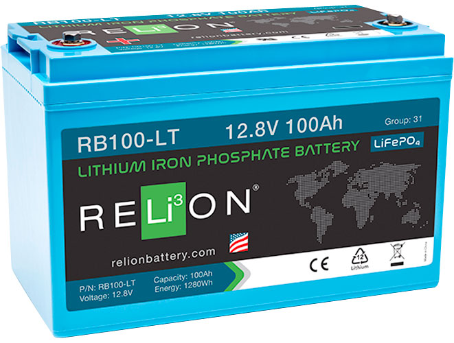
    The Nocqua 10Ah Pro Power Kit is purpose-built for small electronics power on kayaks — a 12V 10Ah LiFePO4 battery with built-in BMS, plug-and-play power cable, and waterproof housing.

    Sizing the Nocqua for your electronics:

    • Garmin ECHOMAP Ultra 2 106sv: ~2.2A
    • LiveScope Plus GLS10 (via Panoptix cable): ~1.5A
    • Total: ~3.7A at 12V → 10Ah × 0.95 ÷ 3.7A = 2.57 hours continuous

    For a half-day trip with live sonar, use two Nocqua 10Ah units in parallel (doubled Ah). For electronics-only use (fish finder + GPS, no live sonar): ECHOMAP Ultra 2 alone draws ~2.2A → 10Ah ÷ 2.2A = 4.5 hours continuous — a full half-day on one 10Ah pack.

    The Nocqua 10Ah is available at Pro Marine Electronics — Marine Power & Rigging Accessories. Critical: Do not charge a LiFePO4 battery with a standard AGM charger — it requires a dedicated LiFePO4 charge profile.

    Failure Mode 2 — Inductive EMI Coupling from Shared Circuits

    The trolling motor’s brushless controller operates via PWM — pulse width modulation — switching at 8–20 kHz. Each switch generates a brief, high-energy voltage spike on the power wire. When your fish finder power cable shares a battery terminal or ground connection with the trolling motor circuit, those spikes ride into the fish finder’s power supply and render as horizontal banding on the sonar image.

    The fix:

    1. Separate battery connections — trolling motor must connect directly to battery terminals, not to a shared bus
    2. Dedicated electronics ground bus bar — all electronics negative leads connect to this bus, which connects via a single heavy wire to the battery negative. Blue Sea Systems model 2104 or 2107 available at Pro Marine Electronics
    3. Ferrite chokes on high-EMI lines if full wiring separation isn’t possible
    4. Fused blade power distribution block (Blue Sea Systems 5026) — individual fused protection per device: ECHOMAP Ultra 2 (with LiveScope) 5A, VHF Radio 5A, Bilge Pump 15A

    Failure Mode 3 — NMEA 2000 Backbone Errors

    NMEA 2000 is a communications protocol that carries navigation and sensor data between compatible marine electronics over a single cable backbone. Every device connects via a T-connector and drop cable. The backbone has two terminators — one at each end. Without proper terminators, the network fails entirely or produces intermittent dropouts.

    The Garmin NMEA 2000 Starter Kit includes backbone cable, T-connectors, terminators, and a power injector — everything required for a small boat. Available at Pro Marine Electronics.

    NMEA 2000 sizing rules:

    • Total LEN (Load Equivalent Number) on a backbone cannot exceed 12 per standard 2A power injector
    • Maximum drop cable length: 6 meters (19.7 ft) per device — longer cables cause impedance issues and intermittent dropouts
    • Terminator at each end of the backbone — if you extend the backbone, move the terminator to the new end
    • Backbone power injector on the electronics fused bus, NOT on the main starting battery

    Failure Mode 4 — Physical Display Damage and Screen Abrasion

    RMP Tempered Glass Screen Protectors

    RMP (Russell Marine Products) tempered glass screen protectors for Garmin, Humminbird, and Lowrance fish finders use 0.3mm tempered glass — optically clear (no rainbow interference patterns), scratch-resistant to 9H hardness, and UV-stable. Installation critical detail: clean the display with a microfiber cloth and isopropyl alcohol before applying — any grit particle under the glass will create a pressure point.

    Available for ECHOMAP Ultra 2 (all sizes), HELIX 12 and 15, HDS PRO 12 at Pro Marine Electronics — Marine Power & Rigging Accessories.

    Standard Horizon HX891BT — Handheld VHF for Every Fishing Boat

    The HX891BT is a floating, submersible (IPX8 to 5 ft for 30 minutes) handheld VHF with Bluetooth connectivity. The Bluetooth connects to the Standard Horizon companion app for DSC positioning — if you trigger DSC distress, your GPS coordinates transmit automatically to the coast guard and other equipped vessels. For kayak anglers: the HX891BT clips to a PFD and stays on you — a capsized angler separated from the boat cannot reach a fixed-mount VHF. Available at Pro Marine Electronics.

    Clean Power Rig Checklist

    Wiring: Trolling motor circuit isolated from electronics | Electronics on separate fused bus | All electronics negatives to ground bus bar | Wire gauge verified per circuit length | All connections marine-grade tinned copper, adhesive heat-shrink sealed

    NMEA 2000: Terminator at each end of backbone | Total LEN under 12 per power injector | No drop cables exceeding 6 meters | Backbone power injector on electronics fused bus

    Sonar: Transducer cables routed perpendicular to DC power runs | Minimum 15″ separation between trolling motor transducer and console transducer | GLS10/ActiveTarget module in ventilated compartment | Interference rejection in sonar menu set to minimum level that clears banding

    Physical Protection: RMP tempered glass screen protector installed on all displays | Standard Horizon HX891BT handheld VHF aboard and charged

    All products in this checklist available at Pro Marine Electronics — Marine Power & Rigging Accessories.

  • How to Rig a 24V/36V Fishing Electronics Wiring Kit — Preventing Sonar Interference and Voltage Drops

    You can buy a $2,000 LiveScope Plus system, a $1,800 ECHOMAP Ultra 2, and a $1,400 Minn Kota Terrova — and then wreck the performance of all three by running them off the same battery with a single wire gauge that’s too small. Bad wiring causes sonar interference, voltage drops that reduce trolling motor thrust, fish finder reboots at full throttle, and intermittent GPS errors. None of those failures look like a wiring problem to most anglers — they blame the sonar unit or the trolling motor.

    Understanding 24V vs. 36V Systems

    24V Trolling Motor Systems

    A 24V trolling motor circuit uses two 12V batteries wired in series. The motor plug connects to the outer terminals (negative of battery 1, positive of battery 2). Battery sizing for 24V at 80 lb thrust: Full thrust draw ~56A @ 24V = 672W. Practical tournament guideline: 200Ah total (2 × 100Ah) minimum for a full 8-hour day at mixed usage. Lithium (LiFePO4) at 100Ah provides approximately 95% usable capacity vs. AGM’s 50–60% — roughly 50% more effective runtime from lithium at the same Ah rating.

    36V Trolling Motor Systems

    Three 12V batteries in series. Used for 112 lb thrust motors (Minn Kota Ultrex 112, MotorGuide Xi5-105) on heavy or high-speed boats where 24V/80 lb is insufficient. Wire gauge requirement is higher at 36V — full thrust draws ~60–65A.

    The Cardinal Rule — Separate Circuits for Electronics and Trolling Motor

    Never power your fish finders, LiveScope, or chartplotter from the same circuit as your trolling motor. The trolling motor is an inductive load — its brushless motor creates electrical noise (EMI) on the supply line every time it changes speed or direction. That noise propagates through shared wiring directly into your sonar circuits and produces interference artifacts — horizontal banding — on your fish finder image.

    The correct system architecture:

    • Trolling Motor Circuit (dedicated): 60A auto-reset breaker at battery, 6 AWG wire minimum (4 AWG for runs >15 ft), direct to trolling motor plug
    • Electronics Bus (12V, tapped from Battery 1 only): 15A or 20A blade fuse block, 12 AWG wire from battery to fuse block, individual fused circuit per device (3A–5A per chartplotter/fish finder)
    • Ground bus bar: All electronic grounds tie here, then single ground run to battery negative

    Wire Gauge Guide — Voltage Drop Prevention

    Circuit Current Load Wire Run Minimum AWG
    Trolling Motor (24V, 80 lb) 56A peak Up to 10 ft 6 AWG
    Trolling Motor (24V, 80 lb) 56A peak 10–20 ft 4 AWG
    Trolling Motor (36V, 112 lb) 65A peak Up to 10 ft 6 AWG
    Electronics Bus (12V) 10–15A Up to 15 ft 10 AWG
    Individual Fish Finder 3–5A Up to 10 ft 14 AWG
    Bilge Pump 10–15A Up to 15 ft 12 AWG

    Use marine-grade tinned copper wire only. Untinned automotive wire oxidizes in the marine environment and increases resistance over time.

    Sonar Interference — Identifying and Eliminating the Causes

    1. Trolling Motor EMI

    Manifests as: horizontal banding across the sonar image that pulses in sync with motor speed changes. Fix: Separate circuit. If you can’t separate the circuit, install a ferrite choke on the trolling motor power lead at the battery connection.

    2. Multi-Transducer Cross-Talk

    Manifests as: ghosting arches on 2D sonar, repeating false-bottom returns. Prevention: Separate your trolling motor transducer from your console transducer by at least 15 inches. Separate two transducers operating at similar frequencies by at least 24 inches.

    3. Voltage Drop / Unstable Supply

    Manifests as: fish finder reboots when the trolling motor goes to full speed, sonar image blanks out for 1–2 seconds. Fix: Correct wire gauge per the table above. The reboot-at-full-throttle problem is 100% a wiring problem in 95% of cases.

    4. Bilge Pump and Aerator Noise

    Manifests as: intermittent sonar noise with no predictable pattern. Fix: Run bilge pump and aerator on isolated circuits with their own fuse block, NOT on the electronics bus.

    Common Wiring Mistakes

    • Using automotive wire: Untinned copper oxidizes at crimped connections within 12–18 months. Always use marine-grade tinned copper.
    • Grounding to the chassis: Fiberglass boats have no chassis ground. All negative leads must return to a dedicated ground bus bar connected by a single heavy wire to the battery negative.
    • Daisy-chaining fuses: Running the chartplotter power from the trolling motor circuit breaker means the chartplotter shares the trolling motor’s supply path — exactly what causes EMI interference.
    • Installing the GLS10 in a sealed compartment: The LiveScope black box generates heat in operation. Mount in a ventilated compartment with airflow.
    • Undersized series jumper: The series jumper connecting Battery 1 positive to Battery 2 negative carries the full trolling motor current (up to 56A). This jumper must be 6 AWG or heavier.

    Products Referenced in This Guide

    All products mentioned here are available at Pro Marine Electronics:

    Questions about wiring a specific configuration? Contact us directly — we help anglers spec their systems before purchase so the first installation is the right installation.